
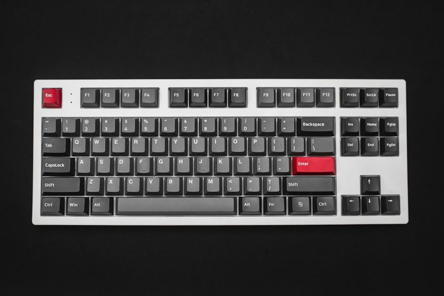
Building a custom mechanical keyboard is more than a hobby; it’s a rewarding blend of hardware tinkering and software mastery. In this guide we’ll walk you through every stage—from selecting switches and PCBs to flashing QMK firmware—so you end up with a truly personal typing experience. By the end, you’ll not only have a functional keyboard but also the confidence to tweak layouts, add lighting effects, and troubleshoot any hiccups.
What You’ll Need
- Keyboard case (plastic, aluminum, or 3D‑printed)
- PCB that matches your case (ANSI/ISO, 60%, 65%, etc.)
- Switches (Cherry MX, Gateron, Kailh, etc.)
- Keycaps (compatible profile)
- Soldering iron (30‑40 W) with fine tip
- Solder (lead‑free 0.6 mm recommended)
- Desoldering pump or wick (for mistakes)
- Wire cutters / tweezers
- Micro‑controller firmware source (QMK)
- Computer with Git, Python, and QMK CLI installed
- Optional: RGB LEDs, stabilizers, lubing kit
Step 1: Planning Your Layout and Ordering Parts
Before you heat the solder, decide on the layout. Popular choices are 60% (compact), 65% (adds arrow cluster), or TKL (tenkeyless). Use keyboard layout editors like layouteditor.com to map keys and generate a QMK keymap file. Once the layout is locked, order the PCB, case, switches, and keycaps from reputable vendors (KBDfans, Drop, NovelKeys). Double‑check that the PCB’s mounting holes align with the case and that the switch footprints match your chosen switches. Ordering a few extra switches (5‑10%) saves time if you encounter dead switches later.
Step 2: Preparing the PCB – Stabilizers and Diodes
When the parts arrive, start with the PCB. Install stabilizers (usually Cherry‑style or Costar) on larger keys (Enter, Space, Shift, Backspace). Clip the stabilizer legs to the appropriate holes, then insert the stabilizer inserts. If you prefer smoother operation, lubricate them with a thin layer of Krytox 205g0. Next, locate the diode orientation—most PCBs have a stripe indicating the cathode. Insert each diode (if not pre‑soldered) with the stripe facing the correct side. Solder each diode quickly to avoid overheating the pads; a 2‑second touch is sufficient. Verify continuity with a multimeter before moving on.
Step 3: Soldering Switches
Place the switches into the PCB sockets, ensuring the pins face down. Use a small piece of tweezers to align any mis‑placed switches. Heat your soldering iron to ~350 °C (for lead‑free solder) and apply a small amount of solder to the tip. Touch the tip to the pad, then feed solder so it flows around the pin and pad, forming a shiny cone. Repeat for all four pins of each switch. After soldering, give each switch a gentle wiggle to confirm a solid joint. If a joint looks dull or cracked, re‑heat and add a touch more solder.
Step 4: Assembling the Firmware Environment
While the hardware cools, set up your firmware workspace. Open a terminal and run:
git clone https://github.com/qmk/qmk_firmware.git
cd qmk_firmware
python3 -m pip install --user qmk
qmk setup
The qmk setup command creates a ~/.qmk folder and pulls the latest QMK files. Copy your layout JSON from the layout editor into keyboards/your_board/keymaps/your_name. Edit keymap.c to define layers, tap‑dance, or custom macros. For example, to set a dual‑function Esc/Fn key:
#define ESC_FN LT(_FN, KC_ESC)
Compile the firmware with:
qmk compile -kb your_board -km your_name
If the build succeeds, you’ll find a .hex (or .bin) file in the _compiled folder.
Step 5: Flashing the Firmware
Most modern PCBs use a DFU or QMK Toolbox compatible bootloader. Put the keyboard into bootloader mode—usually by holding the reset button while plugging in USB or by shorting the BOOT pins. Then run:
qmk flash -kb your_board -km your_name
If you prefer a GUI, download QMK Toolbox, select the compiled file, and click “Flash”. Watch the console output; a successful flash ends with “Done!”. If you see “Device not found”, re‑enter bootloader mode or try a different USB cable.
Step 6: Final Assembly and Testing
Once the firmware is verified (test each key with an online key tester), mount the PCB into the case. Secure it with screws or the case’s built‑in clips. Snap on the keycaps, making sure each is seated fully. If you have RGB LEDs, connect the strip to the PCB’s LED header and configure the lighting in config.h (e.g., #define RGBLIGHT_ENABLE). Power up the keyboard and run a few typing sessions to confirm comfort and functionality. Adjust keycap pull‑down force or lubed stabilizers if any keys feel gritty.
Common Mistakes to Avoid
• Skipping diode orientation checks—reversed diodes cause “ghosting”.
• Using too much solder—creates bridges that short columns.
• Forgetting to update QMK submodules (git submodule update --init --recursive) before compiling.
• Not grounding the case before soldering, which can lead to static damage.
• Ignoring firmware size limits; complex keymaps may exceed the MCU’s flash.
Tips and Tricks
• Use a soldering iron with temperature control; 350 °C is a sweet spot for lead‑free solder.
• Pre‑lubricate switches and stabilizers for a smoother feel.
• Keep a spare set of switches; a single dead switch can stall the whole build.
• Enable “NKRO” in QMK to allow unlimited simultaneous key presses.
• For wireless builds, consider the nRF52 or ESP32‑based PCB and add #define BLE_ENABLE to your config.
Frequently Asked Questions
Can I use a different firmware than QMK?
Yes. VIA, VIA‑compatible firmware, and TMK are alternatives, but QMK offers the most community support and feature set for custom keyboards.
My keyboard isn’t registering any keys after flashing—what’s wrong?
First, verify the bootloader mode was successful. Then check the compiled .hex size; if it exceeds the MCU’s capacity, trim unused layers or macros. Finally, run qmk console to view live key events and spot hardware issues.
Do I need to solder the LEDs separately?
Most RGB‑ready PCBs have LED pads already wired. You only need to solder the LED strip’s connector if it isn’t pre‑installed. Ensure the voltage matches (5 V for most WS2812 strips).
Conclusion
Building a custom mechanical keyboard blends craftsmanship with code, giving you a tool that feels uniquely yours. By following this advanced guide—planning the layout, meticulously soldering, configuring QMK, and flashing the firmware—you’ll end up with a reliable, high‑performance keyboard that you can continually evolve. Happy building, and enjoy the clicks of your own creation!
Photo by JL Cabrera on Unsplash


